2024; Quadruped HIL Simulation
- Guining Pertin
- Sep 8, 2024
- 3 min read

Updated: Mar 15
About the Project
This was a project I started working on but due to time constraints I couldn't fully complete. However, I think it is still worth writing down about it. This was about making a quadruped simulation model in MATLAB which I was planning to use for some downstream research work like RL algorithms.
Hence, I started with building the quadruped model from scratch in Simscape multibody and then using ROS to communicate with the true Unitree Go 1 EDU quadruped for a hardware-in-the-loop simulation.
The Quadruped
Simscape model
We start by building the actual quadruped model in CAD. Then, a rough model of the Unitree Go1 Robot was built from scratch in Simscape Multibody (since I am accustomed to MATLAB more than Python simulators). The main body has the COM frame and different connection frames for each limb provided by rigid transformations (rotation+translation). The limbs are also constructed as rigid bodies with revolute joints between the body, and knee-ankle links that can be actuated through torque commands.

There is one body frame placed at the center of mass of the main body called B. The hips where the limbs are connected are represented by frames H_i, i=1,2,3,4, placed at positions B_p_H_i from the COM. The feet positions are then calculated with respect to these hip frames for each limb.

Analytical Inverse Kinematics

Each limb can be considered as a robotic manipulator in 3D with 3 joints, two near the hip for 3D rotation and one for the knee. The link lengths are d=55mm, L_1=210mm, L_2=210mm. Then, for this iteration, I calculated the inverse kinematics (only position) to convert the foot position (end effector) in (x,y,z) with L_1^2 + L_1^2 >= ||[x,y,z]|| from the hip frame to joint angles (q_1, q_2, q_3) purely through geometrical considerations as

PD Control
For this, the joint angles are also considered in R since it is rigidly constrained to be within [0, pi] after shifting from the default ranges (which can also be negative). Each joint is provided with a PD controller that can track the desired joint angle with a desired joint velocity of 0 as

Body Orientation
Previously we looked at the joint control for the limbs. But by varying the feet positions from the hip frame, we can also control the body orientation. Say H_i_p_F_i^0=(x_i,y_i,z_i) is our initial foot position for each foot and we want to orient the body from W_R_B^0 to W_R_B^f placed at world position W_p_B then we can perform the following:
Convert initial foot position from hip frame to world frame to keep it fixed:

Calculate new foot position based on the new orientation and push this through inverse kinematics:

Testing the Inverse Kinematics
Circular motion
The images below show the limbs following the given 3D circular paths for the foot. Body is rigidly attached and only the limbs are free.
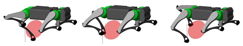
Crouching
In the image below, the (x, y) position for each foot is fixed but only the z value is varied as a sine wave, which in turn forces the quadruped to perform crouching movement. Thebody has a 6DOF free joint to allow it to move around.

Performing Yoga
Based on the rotation matrix for the final orientation of the main body, we can find new foot positions wrt hip such that the feet stay in the same position but the body orientation changes.

Hardware-in-the-loop

To use HIL simulations, I disable the internal Raspberry Pi in the Unitree Go 1 and run a ROS2 node that uses unitree's C++ API to send and receive data between the laptop and the low level controller in Go 1. This node runs in the background while MATLAB/Simulink connects to it using another ROS2 node. While I could've just connected MATLAB directly using with API, it would've been way more difficult trying to compile everything into mex so that Simulink can run it (even if MATLAB can run it, it does not guarantee Simulink can run it easily).
Unfortunately this model is being used for other research work and cannot be publicly shared.


Comments